| |
||
GLOBAL POSITIONING SYSTEMQUICK LINKSSoftware Description - GPS logger module operation - Customisation - Saving power - Fast Start Guide - GPS usage tips OVERVIEWThe TDS2020GDL is a combination of the following. No memory card is included.
q TDS2020F-SP Starter Pack for TDS2020F card computer q TDS2020CM2 PCMCIA adapter q RAM512K cache memory for flash cards q TDS2020CFA Compact Flash adapter q GPS-SAPPHIRE a hemispherical GPS receiver, with voltage regulator IC and connection diagram
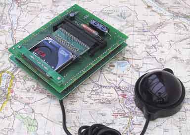
TDS2020F data logger and GPS receiver The main features of this data collection system are
q Log other data as well as location information q Industry-standard PCMCIA and Compact Flash cards q Low power q Output to Excel spreadsheet or Access database q Use any GPS receiver, or this one q When the logger goes into standby it can switch off the Sapphire GPS receiver to save power.
Application areas include agriculture, security, transport, boats etc. Information that can be logged includes longitude and latitude, date and time, pressures, temperatures, rotation rates, flow rates, linear or rotational position, doors open/closed etc. To recover data you can read the card in a PC, upload through a serial port or read the data directly into Excel spreadsheet.
The GPS receiver provided is housed in a hemisphere and the unit has overall dimensions 62 x 50 x 27mm. The base is strongly magnetic so that the receiver can be used on the roof of a vehicle. The connecting wire is 1.3m long and has four flying wire connections for transmit, receive, +5V and ground. Current consumption is 180mA typical. A circuit shows how to connect together a voltage regulator, GPS receiver and the TDS2020F. Included is the ability for the computer to turn off the GPS receiver to save power. The unit outputs NMEA GPS data at 4800 baud suitable for processing by library routines in a TDS2020F embedded computer.
Because a keypad and graphics display can be added, the module may be turned into a complete portable instrument, not just a device to record measurements. Adding other ready-made software modules or custom software can make the system do control work at the same time as data collection. The two serial ports and optional Controller Area Network (CAN) bus interface give it communications capability. GPS SOFTWARE DESCRIPTIONLibrary file #GPSLOG.TDS provides data logging from a GPS receiver. Data from a GPS receiver is scanned for valid latitude, longitude and time. The TDS2020F clock is updated from the time received and the position is continuously logged. Data is collected on to any of the following:
q Compact Flash card in a TDS2020CM2 adapter with TDS2020CFA converter. q PCMCIA-ATA Flash card in a TDS2020CM2 PCMCIA adapter q PCMCIA-ATA hard disk in a TDS2020CM2 PCMCIA adapter
The recorded data is in Comma Separated Variable (CSV) format for direct entry into Excel PC spreadsheet or a database. The GPS receiver can be any type that emits National Marine Electronics Association (NMEA 0183) sentences. Most have this capability. While logging GPS data, values of analog and/or signals at TDS2020F inputs may be also collected in Excel/database format. Information about the card's local environment can later be correlated with its position. GPS LOGGER MODULE OPERATIONThis is an extract from the default NMEA messages provided by the Sapphire Global Positioning System receiver:
$GPGSV,3,3,10,13,10,321,,01,08,292,33*7B
The library software uses the RMC messages to provide the data to be collected. The others are unwanted and discarded. The above sample contains three $GPRMC messages, during data logging the following will be displayed via serial Port 1:
13.10.00 12.03.02 -1.341360,54.232728,0.000,0.0,.548611,37327,
Of the data displayed, only the four Comma Separated Variables (CSV) are sent to the PCMCIA card. They represent
q Longitude in decimal degrees (negative for West of Greenwich) q Latitude in decimal degrees (negative for the Southern hemisphere) q Speed in miles/hr q Heading degrees true q Time in Excel format q Date in Excel format
Date and time are logged in a form understood by Microsoft's Excel spreadsheet. In Excel, dates are days. They start from 1 Jan 1900 (day 1) and times are fractions of a day, for instance, 0.75000 represents 6pm. For initial display purposes the TDS2020F clock is also presented in a readable format at the start of each line. After the logged file is opened in Excel, and date and time columns are correctly formatted, the data received above will look like this:
-1.341360 54.232728 0 0 13.10.00 12-Mar-02
An alternative logging format is still CSV, but the position is stored as degrees, minutes and seconds of an arc. The display is like this during logging:
11.12.98 10.24.43 1,20,29,W,54,13,58,N,36140,.43383, 11.12.98 10.24.44 1,20,29,W,54,13,58,N,36140,.43384, 11.12.98 10.24.45 1,20,29,W,54,13,58,N,36140,.43385,
After import into Excel, the second format data will look like this:
54 13 58 N 1 20 29 W 11-Dec-98 10:24:43 54 13 58 N 1 20 29 W 11-Dec-98 10:24:44 54 13 58 N 1 20 29 W 11-Dec-98 10:24:45
From such recorded data a chart can be produced using an Excel spreadsheet showing the scatter of logged data points. The diagram shows the plot of readings taken at the Thirsk Development Centre in England. The horizontal scale is about 13 metres (14 yards) at this latitude and vertically 11 metres (12 yards) per grid line. For greater positional accuracy differential GPS equipment may be needed.
Development Centre, Thirsk, UK using GPS-SAPPHIRE by the window
At each record, the clock of the TDS2020F is set from the received date and time. This UTC time is based on time at the Greenwich meridian, without any correction for daylight saving time. The main application loop is in GPS-LOG . Before entering the loop one record of the GPS data is examined (but not logged) in order to set the TDS2020F clock. Then progress is held up inside word O'CLOCK until a rounded time arrives. Suppose that we want to log every hour and the instrument is turned on at 6.43, it would be inconvenient to log at 6.43, 7.43, 8.43 etc. Instead, the main loop will be entered at 7.00 so that subsequent records will be taken at 8.00, 9.00 etc. Take another example-logging every 5 minutes. If we start at 8.43, data will be logged at 8.45, 8.50, 8.55 etc. During the initialisation, while in O'CLOCK , the TDS2020F goes to standby, but wakes up every second to check if the rounded time has arrived. Once in the main loop, the unit is in standby most of the time, waking up only to log a record and then going back to low power mode. Mostly, the module will be consuming around 200µA current. GPS SOFTWARE CUSTOMISATIONThe library software can be customised in many ways. The most straightforward are listed here, but almost any requirement can be met.
q In the word INITIALISE , delete the comment mark in front of USA to get North American formatted dates. q Edit the word INITIALISE to give the required logging interval. Without further changes we suggest it should be at least every 20 seconds, but could be every 5 minutes, four times a day, every week or any regular interval q To omit logging of date, time or both, edit the word LOG . q To log speed in km/hr or knots change the scaling constants in the word GPS . q To log altitude in meters eliminate the scaling in the word GPS .
In your application, be sure to put GPS-INIT in the word executed at power-up to initialise serial Port 2. Some systems, like GPS-SAPPHIRE shipped by us after 26 July 2004 or Rockwell's Jupiter LP GPS receiver, do not incorporate RS232 line driver/inverter chips. The signal is like RS232 but inverted and typically 0 to +4V (0V in the steady state). Port 2 of the TDS2020F can receive these signals provided the inversion is done in software. See the commented out lines 'alternative for inverted polarity' in file #SERIAL2.TDS. While the TDS2020F as a receiver is straightforward, as a transmitter you need both the inversion and signal limiting to 0V and +5V. This can be done with a 1k resistor from the TDS2020F output to the receiver input and two Schottky clipping diodes at the receiver input to the 0V and +5V power rails. Again, see the lines 'alternative for inverted polarity' in the serial Port 2 software. SWITCHING OFF THE GPS RECEIVER TO SAVE POWERIf the interval between readings will be 30 seconds or more you can switch off the GPS receiver to save power. Search for occurrences of +++ in this file and uncomment as marked there. Port 9 bit 7 (pin c12) is then an output controlling power to the GPS receiver with logic 1=power on, 0=off. A circuit diagram shows how this can be used to shut down a voltage regulator supplying power to the Sapphire GPS receiver (or similar). See the circuit below. If the logging interval is less than 30 seconds, keep power on the GPS receiver. If power is cycled too often there may not be time to get a position fix. RESOURCES USEDThis software uses serial Port 2 for input of data from the GPS receiver. FAST START GUIDE1. Prepare a TDS2020F computer with a 128k or 512k RAM in the 32-pin socket and a Xicor 28HC256 Flash-EEPROM in the 28-pin socket. No links need be changed from the delivery condition.
2. Add a TDS2020CM2 PCMCIA adapter over the TDS2020F and insert a PCMCIA hard disk, a Flash-ATA or Compact Flash card (using the TDS2020CFA 50 to 64-pin converter).
3. Connect the data-logging module to the GPS receiver. The receiver should provide RS232 data in NMEA format at the standard 4800 baud.
Sapphire GPS receiver connections 4. Put the GPS receiver into NMEA mode, for instructions see its own documentation. The library software only listens to the NMEA sentences but by adding another wire to transmit from serial Port 2 to the GPS receiver you can send native instructions in the initialisation to force it into NMEA mode.
5. If you are using GPS-SAPPHIRE shipped by us after 26 July 2004 you must edit file #SERIAL2.TDS as described under 'No RS232 driver' in the file. This also applies to some other GPS receivers, for example Rockwell's Jupiter.
6. If you are using GPS-SAPPHIRE or different receiver that you can power-down under software control you must edit file #GPSLOG.TDS as described under 'Switching off the GPS receiver to save power' in the file.
7. Compile the file #GPSLOG.TDS. We suggest you try the supplied file before customising it in any other way except as above. Other files in the library are called as compiling progresses.
8. You can now confirm that the GPS receiver is providing good data. Type SET START then GPS-INIT 2WAY and return to make the TDS2020F act transparently. Messages from the GPS receiver should now be seen on the PC. They look like those shown under GPS LOGGER MODULE OPERATION, page 321. To quit this operation press ctrl+C.
9. Prepare the PCMCIA or Compact Flash card by typing HARD-FORMAT and return. This gives single partition in Windows/DOS format and an empty file DATA.FIL.
10. To start logging data, type GPS-LOG and return. Have patience, the library file logs every 20 seconds and you need to wait a couple of minutes to ensure that the data seen on the PC from serial Port 1 is good.
11. To exit from the loop keep your finger on any PC key for a whole logging interval.
12. After logging data, put the PCMCIA card into a PC, typically a notebook and open Excel. An adapter CF-PCA is available for Compact Flash cards.
13. Choose 'File' then 'Open' and select the file DATA.FIL on the PCMCIA card. Click 'next', then check the 'comma' box because the file is comma delimited, then 'next' twice then 'finish'.
14. The third and fourth columns represent date and time so those need to be formatted. Right click on the letter at the top of column 3, choose 'Format Cells', then 'Date' then the form of date required. Formatting the time column is similar. The spreadsheet can now be saved. The spreadsheet should look something like this:
15. Finally you can customise the file #GPSLOG.TDS and collect data from the GPS receiver in exactly the way you want. GPS USAGE TIPSThe GPS signal will be affected by weather and other environmental conditions. Use the receiver with the best possible view of the sky. If it must be indoors, the receiver should be by the window. The following will adversly affect performance:
q solar film on windows q high buildings q bridges or tunnels q high voltage cables q computers, electronic equipment, mobile phones or masts q rain, snow or heavy clouds
When you switch off the power between fixes to save power the next fix takes longer. Keep power on the receiver unless the power-saving technique is really important.(see section 'Switching off the GPS receiver to save power' in file #GPS.TDS). If you do remove power, allow as long as possible - preferably minutes - for the next fix. This is especially important if the receiver is moving. |
 |
|