| |
|
|
STAND-ALONE SYSTEMSSUMMARY PROCEDUREThe TDS9092 is designed so that it can be incorporated into products. Forth compiled code can be put into PROM making the software a permanent feature of the system, even if the power removed. This section assumes that your application is now working from RAM and that you wish to program a PROM.
q Once the application has been debugged in RAM edit in SET WORK at the end of the program. Here we assume the Forth word WORK to be the infinite loop you want the card to execute on power-up. q Switch off the TDS9092 and put the DS1213C non-volatile socket between the middle RAM and the board�s socket. q Power up and compile the program again. q Switch off the TDS9092, move the link from W to X, tying high the read/write pin of the non-volatile RAM to make it look like a PROM. q You can now power-up and directly enter the application. (This is a development facility and field tests should be made with a real PROM; a non-volatile RAM with its write disabled is more susceptible to noise.) q Correct any further software bugs found at this stage, for instance you may get strange behaviour if your variables are not initialised in WORK . Repeat development up to this stage as necessary. q Once any problems have been cleared switch off and remove the DS1213C socket with the RAM still in place and copy it to a 27C256 in a PROM programmer, using an adapter jig if necessary (see later). q Put the PROM into the socket on the TDS9092 and set links appropriate to the PROM. Power up the board and the system should enter your application.
Next, thoroughly check that your application is working correctly. The rest of this section is concerned with alternatives arising from the above summary. PROM types and how to program them are also discussed. HOW COLD START PARAMETERS ARE USEDOn the TDS9092 the dictionary pointer at power-up is hex 083C. Applications code therefore grows from this location. During development, 0000�7FFF has a 32K bit RAM, being replaced by PROM in the end product. The area 0000�07FF is inaccessible and 0800�083B is for an Interrupt Jump Table and Cold Start Parameters, detailed in INTERRUPT JUMP TABLE, and COLD START PARAMETER TABLE. The former has jumps to all defined interrupt code sequences, the latter gives information to the Forth system about what to do when power is first applied � for instance the first Forth word which should be executed. On applying power the Forth software fills the locations with defaults and they are then read back for use in the power-up routines. Unless you change them they will be programmed into PROM with the application code. When the PROM is put in place of the RAM the parameters are made permanent. The word SET makes setting the Cold Start Parameters easy. Use it at the end of the application program to adjust the four parameters which are absolutely necessary (see COLD START PARAMETER TABLE). In practice the following is the usual sequence at the end of debugged application software before programming the PROM. Here it is assumed that the word WORK is in overall control of the product. The last line of the application is given, then setting of Cold Start Parameters:
: WORK BEGIN � (application) � ?TERMINAL UNTIL ABORT ; SET WORK
Other Cold Start Parameters and the Interrupt Jump Table can be changed before programming the PROM, to further customise the system for the application. ASSIGN sets the interrupt jump for any Forth sequence tied to an interrupt. Cold Start Parameters are best accessed using +ORIGIN to give portability to other systems like the TDS2020F. For example
$4000 0A +ORIGIN !
tells the system that the end of dictionary is now hex 4000. ENTERING FORTH FROM THE STAND-ALONE SYSTEMIf a PROM does not work, try recompiling using SET ABORT instead of SET WORK . It should now power up into Forth to allow you to find the program bug. By implementing your program as a loop which can be finished on receipt of a ctrl+C, a terminal can be plugged into the product at any time for maintenance or repair work. The ctrl+C (expected by ?TERMINAL ) will cause the prototype to drop into the Forth system so that variables can be examined or further application words defined. It is useful to structure your software so that the BEGIN � UNTIL loop shown above is fast (a few seconds at most), and response to the ctrl+C will be reasonable in most circumstances. If the outer loop must be slow another way is to include the ?TERMINAL in a low level loop that is passed through very often. Put this in the loop:
?TERMINAL IF ABORT THEN USER VARIABLESWhen a TDS9092 powers up directly into an application there are some system variables which will not be set unless you do so in your initialisation. These are:
BLK IN OUT SCR OFFSET CONTEXT
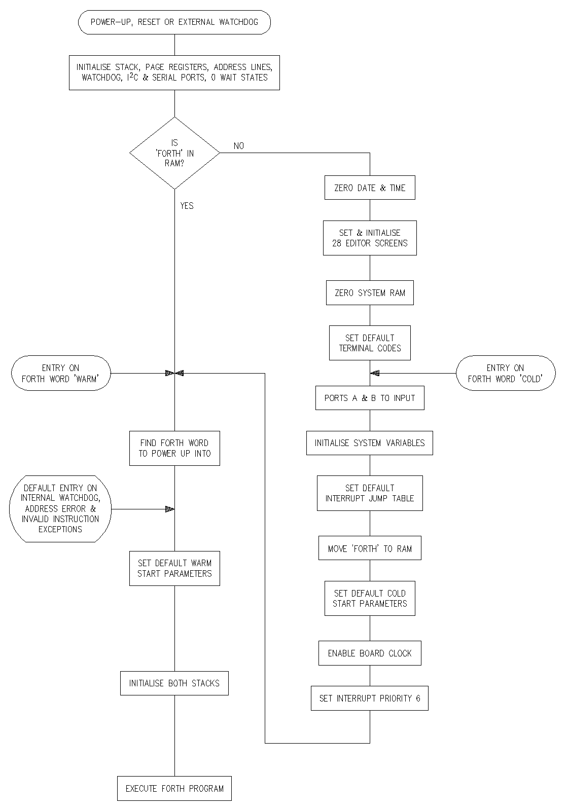
Only expert Forth users are likely to use words which need any of these to be set. If you use WORD , for example, BLK and IN will need initialising. When an application is put into PROM use only the Forth vocabulary. The number base will be decimal at power-up unless otherwise set in your initialisation. COLD START ROUTINEThe flow diagram shows what happens when power is applied to the TDS9092. It also has the actions of reset, internal trap and the words COLD and WARM . Note that even the former is not completely cold, when developing it would be inconvenient to have the clock zeroed for example. Install the utility _DOGCOLD.TDS to make resets or watchdog time-outs do a full cold start.
Cold start routine
UNUSED INPUTSIn a stand-alone system consider each unused input to the TDS9092. For example if STBY* input is free, tie it to +5VOUT . This will avoid pick up of radiated interference. PROM TYPESYou are replacing a 32K byte RAM, normally with a 27C256 PROM. However make sure it is a 27C256, not 27256, to keep the load on the power regulator to a minimum. To be within specification the access time should be 200ns or better. Pin connections are not the same and you need to change over the push-on links:
If after compiling your program the dictionary pointer is less than hex 4000, you have the option of using a 27C128 PROM; if it is less than hex 2000 you can use a 27C64. Type HERE U. to see the dictionary pointer value, and see PCB LINKS for the links required. PROGRAMMING PROMSPROGRAMMING 27C256 PROMSTo put the compiled Forth code into a 27C256 PROM remove the 32K byte RAM and DS1213C non-volatile socket as one unit, read it into a suitable PROM programmer and copy the data into the PROM. Before programming the equivalent 27C256 PROM note that pin connections of RAM and PROM are not the same (unlike smaller ones). If your programmer can read a 32K non-volatile RAM and program a 32K PROM there is no problem. If not there is a jig you can make to solve the problem. Mount two 28-pin sockets on top of each other with all pins connecting except 1 and 27. Make these connections with fine insulated wire (e.g. wire-wrap type):
q Let all pins connect except 1 and 27 q On the top socket bend 27 sideways and solder it to pin 28 (ties high the write line of the NV RAM) q Connect bottom pin 27 to top pin 1 (address line A14)
Plug the DS1213C & RAM combination into the jig and then put the jig in the programmer (in that order), not touching the pins at all. The non-volatile RAM will now look like a 27C256 and can be read into the programmer. The compiled code in memory is in addresses hex 0800�7FFF (max) and since you�re making an image of this, the code should be put to addresses 0800�7FFF in the 27C256 PROM. Note that addresses 0000�07FF are unused. PROGRAMMING 27C128 PROMSTo put the compiled Forth code into a 27C128 PROM, remove the RAM and non-volatile socket as one unit, read it into a PROM programmer and copy the data into the PROM. Some programmers will not directly read non-volatile RAMs, but consult the manufacturer because support for yours might now be available. If not, make up a jig with two 28-pin sockets, one on top of the other:
q Let all pins connect except 27 q On the top socket bend pin 27 sideways and solder it to pin 28
Plug the RAM/DS1213C combination into the jig and then put the jig in the programmer (in that order), not touching the pins at all. Pin 27 is the RAM�s write line, and tied to the +5V rail in the programmer the latter cannot corrupt the RAM. Read the NV RAM as if it were a 27C128 PROM. Never try writing data to an NV RAM with a PROM programmer unless the manufacturer�s data allows it. You will normally damage the device. OTHER WAYS OF PROGRAMMING PROMSTDS961 PROM PROGRAMMERIf you attach a TDS961 PROM Programmer board to the TDS9092, the data can go directly from RAM to PROM without needing the non-volatile RAM. See the section TDS961 PROM PROGRAMMER. The commands to transfer to PROM will be:
q To
27C128: q To
27C256 PROM EMULATORYou can use an PROM emulator which also programs. Set it to type 27C256. Pin a24 is a convenient place to pick up the WR* write signal needed by these emulators. When using an emulator remember you have an PROM emulator, not a RAM emulator, so the links E G Y should be made with F W X Z open. UPLOAD TO A COMPUTERPROM programmers differ in their requirements but here is an example of how to send compiled code up the serial RS232 link. In this case the format has first a control code 02, then a 4 character hex address for a host computer to know where to put the data, then the binary data transmitted as hex characters and, finally, a control code 03. Software in the host computer can receive this and put it into its own memory.
02 CONSTANT BINSTART ( leading control code 03 CONSTANT BINEND ( trailing control code : BINSEND ( TDS9092 address, host address, ( number of bytes BASE @ >R HEX ." Please wait �" CR ( save base BINSTART EMIT ( send start byte SWAP 0 <# # # # # #> TYPE ( send host address OVER + SWAP DO I C@ 0 <# # # #> TYPE LOOP ( send data BINEND EMIT ( send end byte R> BASE ! ; ( restore base
Note that this is only an example. Any format required by a host computer or PROM programmer can be produced in a similar way. COLD START PARAMETER TABLESee HOW COLD START PARAMETERS ARE USED for use of the following table. The word SET alters those entries marked �.
|
 |