| |
|
|
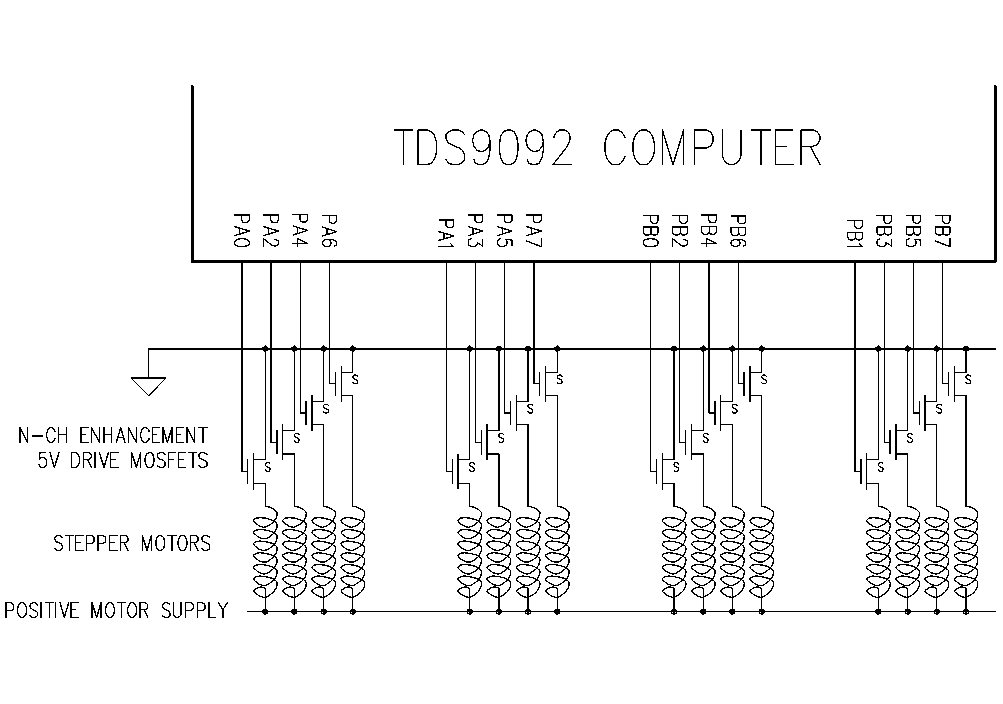
STEPPER MOTORSOPERATIONThe library routine _4STEP.TDS drives four 4-phase stepper motors under interrupt from the TDS9092. Your application code determines direction, speed and number of steps for each of the four motors. All can move simultaneously with different settings. For example
2 -100 250 DRIVE
sends motor number 2 100 steps backwards at a speed of 250 units. The movement is done under interrupt so the microprocessor is not held up while the action occurs. It can be doing other things like writing to a display, monitoring limit switches or creating an acceleration profile. HARDWAREEach of the four stepper motors is connected to either the odd bits or even bits of port A or port B as follows:
A suitable quad driver IC is the SGS-Thomson or Sprague part ULN2068B, or use n-channel MOSFETs as in the circuit, for example type ZVN2106A.
Stepper motor interface PRINCIPLE OF OPERATIONThe output compare interrupt 1 of the 16-bit free running timer is used to generate regular interrupts which decrement a variable for each motor. When zero is reached a bit pattern is rotated and output to the motor. The pattern is organised to generate a 4 phase stepper drive with either full or half steps as selected. Note that no 'stepper driver card' is needed, it is all done in software. CUSTOMISATIONBy default, the interrupt occurs every 256 counts of the 16-bit free running timer i.e. every 208�s. The output compare register is moved forward by 256 counts on each interrupt ready for the next one. You can adjust the interrupt rate to give up to 2400 steps per second. Four motors using ports A and B are driven by this software. You can modify the software to use only the two connected to Port A if Port B is in use for a matrix keyboard. Motors can be run on other ports simply by changing the addresses defined. By such changes any number of motors can be supported. Note that the output compare register 1 of the 16-bit timer is also used in the ASSIGN / RETURN; interrupt driven multitasking mechanism. |
 |