 |
|
|
| |
 |
TDS990 POWER SUPPLY
DESCRIPTION
This product is obsolescent and should not be used for
new designs with a long lifetime.
A universal power supply for microprocessor and other applications.
It provides three voltage supplies of +12V, +5V and -12V. The +12V supply is
adjustable to any other voltage in the range +7.5V to +15.5V. In addition, a
50Hz (or 60Hz) square wave clock derived from the line supply is provided for
microprocessor timing software. Use with either 110-120V or 220-240V line power.
The power supply is single Eurocard size 160 x 100mm and the connector is a
DIN 41612 type C. A 2 Amp fuse is fitted in the positive DC supply rail.
 |
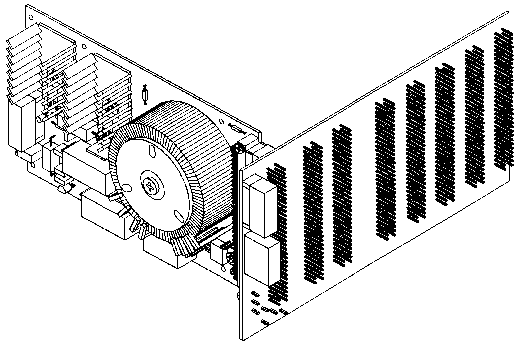
TDS990 Power supply and TDS9099 Backplane
|
CONNECTIONS
|
Pin numbers
|
Function
|
|
|
a1
|
c1
|
+5V 1.7A less current being taken from +8V/+15V permissible).
1.0A max.
|
|
a3
|
c3
|
+15V 0.6A Voltage adjustable by multiturn
|
|
|
|
+12V 1.2A potentiometer at front of board
|
|
|
|
+10V 1.7A
|
|
|
|
+ 8V 1.8A
|
|
a5
|
c5
|
LED indicator output. Provides a negative current of
about 15mA. Connect a Power On LED from this pin to a32/c32 if required
|
|
a7
|
c7
|
PCB screen. Connect to ground
|
|
a10
|
c10
|
First 120V Primary Input (live)
|
|
a14
|
c14
|
First 120V Primary Input (neutral)
|
|
a19
|
c19
|
Second 120V Primary Input (live)
|
|
a23
|
c23
|
Second 120V Primary Input (neutral)
|
|
a26
|
c26
|
PCB screen. Connect to ground
|
|
a28
|
c28
|
Ground. Connected on the board to a32/c32
|
|
a29
|
c29
|
-12V 0.5A (not fused on DC side)
|
|
a31
|
c31
|
50Hz (or 60 Hz) square wave output, filtered to eliminate high frequency spikes so that correct timekeeping can be maintained
|
|
a32
|
c32
|
Power Supply Common. Usually connect to ground.
|
 |
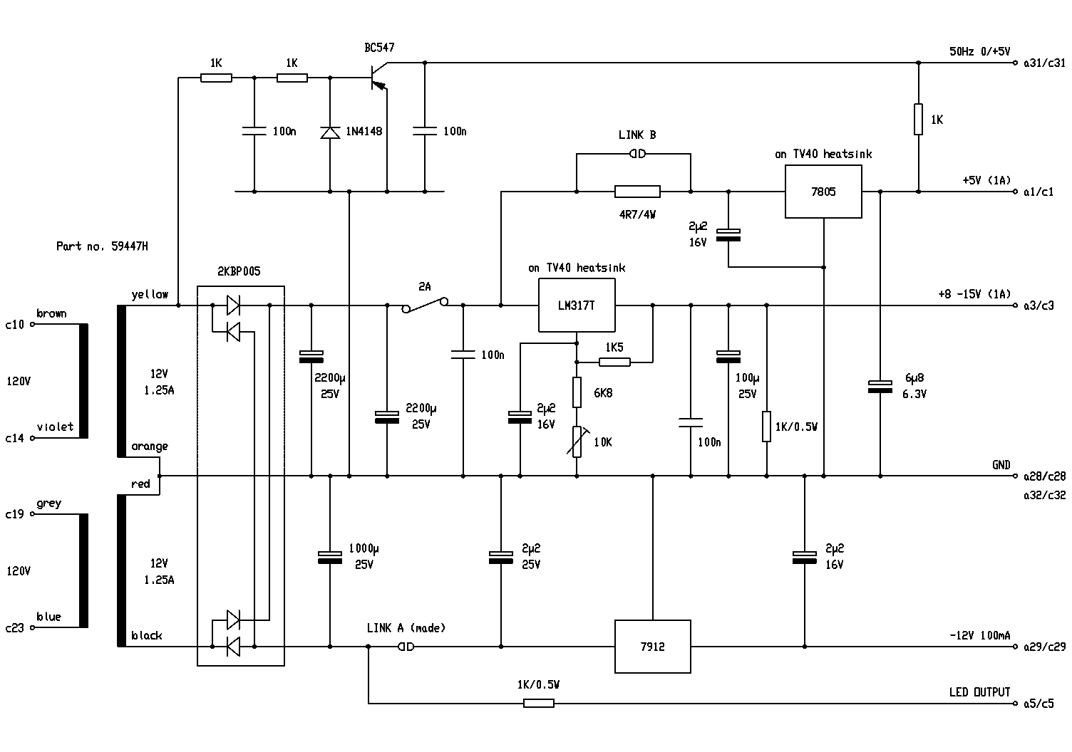
TDS990 circuit diagram
Click the diagram for more detail, or to save a copy:
1. in Internet Explorer right click on the picture and select "Save Target as..."
2. in Netscape double-click the picture to open the file, then under "File" select the "Save As" option.
|
 |


