| |
|
|
STAND ALONE SYSTEMSSUMMARY PROCEDUREThe TDS2020F card computer is incorporated into products. Forth compiled code ends up in non-volatile memory making the software a permanent feature of the system, even if the power is removed. Here is an overview, but it is not complete. You should read all of this section about making stand-alone systems.
q
Do most of the development with a 32k byte RAM in the 28-pin socket. Although
the Flash-EEPROM chip will be used for final compilation, use RAM for initial tests
and during most of the development. Be sure to allow an escape to interactive
Forth from your program.
q
Once the application has been debugged in RAM, put a Xicor 28HC256 32k-byte Flash-EEPROM in place of the RAM chip. The Flash-EEPROM
has a limit of 100,000 write cycles. Also, it is possible to inadvertently apply
a software lock on the device. For these reasons only use Flash-EEPROM once
the program is substantially complete.
q
Ensure you don't have SET WORK in
your source code, it should be typed interactively. Also delete any in-line EIS instruction (if present it should be
inside a definition). Now recompile the source code into Flash-EEPROM.
q
Type SET WORK interactively after compilation. Here we assume the
Forth word
WORK to be the infinite loop you want the card to execute on power-up.
The program starts to execute at once. The Flash-EEPROM has now been protected�it is locked against accidental
writes.
q
Switch off the TDS2020F, disconnect it from both power supply and PC and wait 15 seconds
(more if you have a TDS2020CM2 PCMCIA adapter because of its big capacitor).
q
You can now power-up into the stand-alone application. Check that your application
is working correctly.
q
Escape to interactive Forth
if there is a problem. All the application words are available to you. You can
use them for test and debug. You are still able to turn off and run the program
again at power-up.
q
If you want to start again
from scratch, type COLD interactively. The Flash-EEPROM is unlocked and the existing dictionary
erased. You could now restart from the beginning. Once the prototype is complete, manufacturing can use copies of the Flash-EEPROM or cheaper and lower current 27C256 EPROMs. The rest of this section is concerned with further detail arising from the above summary and alternative ways of working. THE INDEFINITE LOOPA stand-alone program should execute a loop that never ends. The following is the suggested structure of the highest level of any program:
: INITIALISE ( - ) \ Set direction of I/O ports, \ zero all variables, \ including multitasker locks � initialisations � ; : TRY ( - ) \ One pass through the main program loop KEY? IF START THEN � rest of program � ; : MAIN ( - ) \ Indefinite application loop : WORK ( - ) \ Word executed at power-up
Inclusion of KEY? IF START THEN will allow you to escape from the indefinite loop back into Forth even after the application has been closed in Flash-EEPROM. START is Forth�s entry point and any key on the serial link will cause an escape from the program into interactive Forth. If serial Port 1 will be used in the equipment being constructed test something else, for example a parallel port pin. By implementing your program as a loop that can be finished on receipt of a key, a PC or terminal can be plugged into the product at any time for maintenance or repair work. The key (expected by KEY? ) will cause the equipment to escape into the Forth system so that variables can be examined or further application words defined for debugging purposes. If you used the pre-emptive multitasker in the program there is a better way�leave operational tasks without the escape and add Forth itself as a further task. With this arrangement your equipment can function and Forth will be interactive, both at the same time. See the example in FAST START GUIDE TO PRE-EMPTIVE MULTITASKING, page 179. Although MAIN is sufficient for the final loop it is advisable to add a further loop around it to catch any run-time errors as shown above. You can accept the above cookbook suggestion or see ERROR HANDLING, page 144, for more information. FLASH-EEPROMSUse Xicor 28HC256 Flash-EEPROM with the TDS2020F. Some others are superficially the same (e.g. Atmel 28HC256) but are not identical and will not work. While compiling to Flash-EEPROM (but not RAM), interrupts and the internal watchdog are disabled. Even the clock does not increment. Before running any program that uses interrupts you need to lock the Flash-EEPROM by typing SET WORK interactively. To enable interrupts include EIS in the power-up word. A good alternative to SET WORK while debugging is SET START . That gives you interactive Forth at power-up, from where you can type WORK . Be sure you can exit from your program to Forth so that you can use COLD to erase everything if necessary. If you can't escape to Forth, you can't re-expose the Flash-EEPROM for writes. If you get locked out use a library routine to open up the Xicor 28HC256. Move the chip to the 32-pin socket leaving four positions empty towards the edge of the board. Also cut link K and make link J. Compile file #EEPROM.TDS and type EEEXPOSE . HOW COLD START PARAMETERS ARE USEDOn TDS2020F the dictionary pointer at power-up is hex 88A6. Applications code grows from this location. The area 8800-88A5 is for an Interrupt Jump Table and Cold Start Parameters, detailed in INTERRUPT JUMP TABLE, page 170 and COLD START PARAMETER TABLE, page 235. The former has jumps to all defined interrupt code sequences, the latter gives information to the Forth system about what to do when power is first applied�for instance the first Forth word which should be executed. On applying power, the Forth software fills the locations with defaults and they are then read back for use in the power-up routines. Unless you change them they will be programmed into Flash-EEPROM with the application code. The word SET makes setting the Cold Start Parameters easy. Type it interactively after the final compilation to adjust the six parameters that are absolutely necessary. Apart from using SET you can �manually� change Cold Start Parameters and the Interrupt Jump Table to further customise the system to the application. An example is the word ASSIGN which fills in the interrupt jump for any Forth or assembler sequence tied to an interrupt. Cold Start Parameters are best accessed using +ORIGIN to give portability to other systems like TDS9092. For example $FF80 $0A +ORIGIN ! tells the system the end of dictionary is now FF80. If you have not used SET , the Flash-EEPROM can be closed when everything is ready by using the following definition. Then switch off and restart.
CODE PROTECT ( - ) \ Protect Flash-EEPROM from writes B $D555 )) $AA ## MOVIM, B $AAAA )) $55 ## MOVIM, B $D555 )) $A0 ## MOVIM, END-CODE COLD START PARAMETER TABLEThe addresses in the table used by Flash Forth are as follows. The word SET alters those entries marked �.
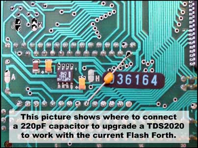
UPGRADING AN OLDER TDS2020Previous TDS2020 users can enjoy Flash Forth. To use it with TDS2020 boards before revision F, a 220pF capacitor (order code CAP220P) should be soldered across the 28-pin socket on your TDS2020 computer. It suppresses an address-decoding spike that is irrelevant to RAMs, but can cause a problem with Flash-EEPROMs. PCB revision F incorporates the capacitor.
Replacing Forth version 3.07A or earlier 1. Solder the capacitor under the 28-pin socket between pins 14 & 20. 2. Replace your H8 microprocessor with the one containing Flash Forth ROM version 4.xx. 3. Proceed as shown in the summary at the start of this chapter.
Adding the upgrade capacitor
Replacing Forth version 3.07 in a TDS2020DV development board If you use the TDS2020DV development board to produce your applications, the compile to Flash-EEPROM facility will not be immediately available to you. However, the Forth ROM version 4.xxDV is still useful to you in two ways:
1. As an update from the current version 3.07. 2. To make a customised H8/532 with part of your program already compiled into the microprocessor. The resulting H8/532 will allow you to compile the rest of the program directly into Flash-EEPROM. See THE PART1/PART2 CONFIGURATION, page 238. EXPANDING THE PROGRAM SPACEAVAILABLE METHODSThe available program space in the Flash-EEPROM is 29k bytes. This can hold quite a large program because Forth is more compact than other languages and a lot of sub-programs such as LCD and keypad support are already pre-compiled into the Forth system. Larger programs can be accommodated in these ways:
q Use the second part of the H8/532 microprocessor by adopting the �Part1/Part2� configuration. This is very important and is described in the next section in more detail. q Off-load text in the program. Messages destined for LCDs can be placed in a PCMCIA-ATA or Compact Flash card or on a Flash chip on the two-wire I2C bus. The latter can be mounted in the 8-pin socket present on TDS2020CM2 PCMCIA and TDS2020CAN (Controller Area Network) adapters. See file #EXTMESS.TDS for details. q Reduce the program size by up to 10% by cutting down the size of stored names from the default maximum length of 31 characters. 3 WIDTH ! at the start of your program will cause definition name MAGIC-POTION to be stored as MAG along with its length of 12 bytes. 9 bytes would be saved in this case. Note that choice of names is important, some names may then clash, CONCERT would match the system name CONTEXT with a length of 3 since only 3 characters and the name length would be checked on compilation. q Use the empty space in the second part of the H8/532 microprocessor for tables such as character shapes for graphics displays. q Use a Flash chip in the 32-pin socket for assembler coded interrupts or in-line parts of the program. Put only a shortened definition in the main dictionary. For example, this calls a subroutine at address hex FF124 in the extended memory: HEX THE PART1/PART2 CONFIGURATIONThe normally empty 16k bytes in the microprocessor are used to hold a stable part of your program, the rest being external in the 28-pin socket as usual. You get
q An extra 16k bytes of compiled code q Faster compilation, a large section having been pre-compiled q All the advantages of Flash Forth in the 28-pin socket q The ability to change the second part of the program at will
Using #PART1F.TDS you make a H8/532 microprocessor customised to your series of applications by combining both the Forth system and your own primitives to make up to 32k bytes of code you burn into the H8/532. Using #PART2F.TDS you make the rest of the program�the part that will be stored in the Flash-EEPROM. The higher levels of the program stored here can be repeatedly erased and re-compiled without any PROM programmer, even remotely.
It is assumed that your application consists of two files:
q PRIMITIV.TDS containing the stable part of your program�Forth words to be used from address hex 4000-7FFF
q
JOB00001.TDS containing the higher level parts of your program�Forth words used
from address hex 8800-FB80 The #PART1F.TDS is used to get Part 1 of the application primitives into an EPROM or H8/532 chip at address hex 4000. It assumes Part 2 of the application program will be compiled using the library file #PART2F.TDS into a Flash-EEPROM in the 28-pin socket at address hex 8800. The Forth version must be 4.xxDV or later, used in a TDS2020DV development board until Part 1 is complete, see MEMORY, page 23. The TDS2020DV is a piggyback board that emulates the PROM inside the H8/532 microprocessor. During development, the TDS2020DV should have a RAM in the middle socket and a Xicor 28HC256 Flash-EEPROM in the end position over the TDS2020F's 28-pin socket. Change no links�F & W should be made on the TDS2020F and W on the TDS2020DV. Once Part 1 is compiled and working you can dispense with the TDS2020DV by copying the Forth ROM and the Part 1 EPROM into a blank H8/532 microprocessor. Put the Flash-EEPROM into the 28-pin socket on the TDS2020F. Here are detailed instructions:
1. Make file PRIMITIV.TDS containing library routines, stable parts of your application and all code using interrupts. 2. Compile #PART1F.TDS, which will include compilation of your file PRIMITIV.TDS. 3. Copy the binary image from hex 4000-7FFF (the middle chip in the TDS2020DV) to an EPROM. You can use the PROM Upload facility of TDS-PC for Windows to make a PROM-programmer file. 4. Power down, put the EPROM in the middle socket and change the TDS2020DV link W to link X. 5. Power up again and Forth should be interactive with the dictionary pointer in the Flash-EEPROM at hex 880C. 6. Make a file JOB00001.TDS with the top-level parts of your application, including a word WORK that is an indefinite loop. It is very important that it includes some way of getting out of the loop to Forth, i.e. to the word START . One way is to use KEY? IF START THEN . 7. Compile #PART2F.TDS, which will include compilation of your file JOB00001.TDS. 8. Interactively, type PROTECT then return. Note that you do not use SET . 9. The full program will now execute and the system is stand-alone. You can power down and back up again. 10. Escape to Forth to do any hardware debugging. All words are available. 11. To erase Part 2 type COLD and you can then compile a new version, restarting these instructions at point 6.
Important notes: q If the applications use the multitasker, include #ROBIN.TDS and #TASKS.TDS in the file PRIMITIV.TDS compiled when making Part 1. This is because the software interrupts they use need to change the interrupt jump table at address 4000-4087. q If the applications contain interrupts include the interrupt routines in the file PRIMITIV.TDS along with the associated ASSIGN statements. EXPANDING VARIABLE SPACERAM ALLOCATION IN A STAND ALONE SYSTEMIt is important to understand the function of the RAM memory inside the microprocessor of a turnkey system. See also ADDRESS MAP 6, page 59.
q FB80-FD7F Used by the Forth system. This half is generally unavailable to you but the stack provided is especially large and if pressed you can use some of the top part of it for extra variables. q FD80-FDA1 Number formatting area. These 34 bytes are used when you output numbers with words like U. . q FDA2-FDF5 In a turnkey system the word PAD returns address FDA2 for use as a scratchpad area up to 84 bytes long. It can be used over and over by different Forth words. It is especially useful for creating complex text strings or analysing input messages. The Forth system does not touch it and if you have not used PAD your program does not need this RAM area. q FDF6-FF7F Used for variables. Unless you deliberately alter the content of VDP , the Variables Dictionary Pointer starts at hex FDF6 when you compile a program. The free variable space when using ANS Forth version 4 from the microprocessor is 394 bytes, equivalent to 197 16-bit variables. MORE VARIABLESThese are the alternative options if 197 variables are not sufficient. See also EXTRA VARIABLES, page 198.
q
Add RAM in the 32-pin socket to give up to 262,144 variables.
q
To increase the variable space from 394 to 478 bytes, change the position
of the Variable Dictionary Pointer ( VDP ) before
starting program compilation: q Use the TDS2020DV development board as a piggyback, with the ANS Forth ROM version 4.xxDV. This variant of the kernel builds up the definitions dictionary from address hex 4000 and variables dictionary from hex 8800. It means you have 16k bytes of available program space and 29k bytes (from 8800 to FB7F) for variables. q Develop with the TDS2020DV as above, but then dispense with it by copying the Forth ROM and your application EPROM into a blank microprocessor. q Use a chip on the I2C bus for more variables, see USING CLOCK CHIP RAM, page 120. TDS2020CM2 and TDS2020CAN adapters have empty sockets that will take 32k byte EEPROM chips. See library file #24WC256.TDS. FORTH VERSIONSStarter Packs usually have ANS Forth version 4.xx blown into the first half of the 32k-byte microprocessor PROM. When a TDS2020DV development board piggyback is added, its sockets at hex addresses 00000 and 04000 override the PROM in the microprocessor. Usually the ANS Forth ROM version 4.xxDV is put in it, but version 4.xx will also work. For details on the different memory use, see ADDRESS MAP 2 and ADDRESS MAP 2A, page 54. These are the trade-offs: ADVANTAGES OF VERSION 4.xxq Flash Forth�direct compilation into Flash-EEPROM�only works with version 4.xx. q Version 4.xx is important when you can�t keep the TDS2020DV development board in place during field trials for mechanical reasons, for example with the TDS2020CM2 Card Memory board installed. q Software that must be frequently changed is in a cheaper Flash-EEPROM or EPROM rather than in the one time programmable microprocessor PROM, yet without the height and cost of a TDS2020DV development board. q Because the Forth is in the microprocessor, this method gives faster execution than the TDS2020DV even though it is not as good as that achievable by putting everything in the microprocessor PROM. ADVANTAGES OF VERSION 4.xxDVq When using the multitasker, 4.xxDV has enough RAM for (potentially) 77 tasks. With 4.xx there is only enough RAM left for 2 to 4 tasks�see TASK RECORD LAYOUT, page 195. q All the microprocessor PROM can be used with or without the PART1/PART2 CONFIGURATION, page 238. q With the application program inside the microprocessor the code can achieve full potential speed from the board. With the program external in the 28-pin socket version 4.xx runs at 60-90% of maximum speed. q There is usually no need for a RAM in the 32-pin socket because 29k bytes are available for variables in RAM in the 28-pin socket.
To distinguish the Forth versions there is a suffix �DV� on the one that needs TDS2020DV during development, e.g. 4.02DV. Most software will compile directly and work on either 4.xx or 4.xxDV but you will have to change any references to the interrupt jump table (unless the +ORIGIN method is used to avoid absolute address references, see table below). E.g.
COLD START FLOW DIAGRAMThe flow diagram shows what happens when power is applied to the TDS2020F. It also has the actions of reset and the word COLD . Note that even this is not completely cold, when developing it would be inconvenient to have the clock zeroed for example. Install the utility #DOGCOLD.TDS to make traps do a full cold start. COLD START FLOW DIAGRAM
Cold start routine IF THE PROGRAM DOES NOT WORKTest your program as much as possible before committing to PROM. If it works in RAM but not Flash-EEPROM consider these common mistakes:
q SET WORK was not used before switching off. q Variables not initialised at power-up. Make sure that the program writes something, perhaps zero, to each variable before it is used, otherwise each will have a different value every time you turn on the TDS2020F reflecting random states of the RAM. Do not forget to zero lock bytes in multitasking systems.
If you used a RAM instead of Flash-EEPROM and then transferred the compiled code to EPROM there are further easily made errors:
q The EPROM is not an exact copy of the RAM. Compile again in RAM and look at the first few bytes in the program, for instance with $8800 $140 DUMP . Now do the same with the EPROM, using the facilities in the PROM programmer. You may see that a corruption has occurred in the transfer. q The RAM data was not transferred to the equivalent place in the PROM. A common mistake when using Forth version 4.xx is to take the data at hex 8800 upwards and program it into a 27C256 EPROM from address 0000 instead of 0800.
If the program does nothing despite these checks, recompile using SET START instead of SET WORK . It should now power up into Forth to allow you to find the program bug. UNUSED INPUTSIn a stand-alone system consider each unused input to the TDS2020F. To avoid pick up of radiated interference. Both STBY* and NMI* inputs have 100k resistors up to +5V but in high electromagnetic field environments (like a TDS2020F controlling a transmitter) these may not be low enough. Note that the NMI* input is also driven by an open drain from the clock chip so do not tie this line directly to +5V, always use a resistor. Apart from electromagnetic effects, when using low-power standby modes the indeterminate state of an input can increase power consumption leading to shorter battery life. ADDING A LITHIUM BATTERYThe TDS2020BYN battery board fits directly on a TDS2020F computer (or as a third level above a TDS2020F and TDS2020DV pair because of its long pins). Alternatively connect a TDS2020BYD externally by just 2 wires to pins VBATT (pin z3) and GND (pin c32). The lithium battery is protected by a blocking diode on the TDS2020F. There are 33k limiting and 10M shunt resistors on the TDS2020BYN and TDS2020BYD. Similar safety precautions should be taken if you use a different lithium battery connected externally to pins VBATT and GND. The battery connected to VBATT keeps alive the clock chip and RAM in the 32-pin socket. Note that it does not maintain any applications program. USING EPROMSHARDWAREDevelopment is most easily done with Flash-EEPROM, but for production a 27C256 EPROM is preferable because it is cheaper and the current consumption during standby is lower. You may also want to blow EPROMs if you used a RAM instead of Flash-EEPROM or did the development using TDS2020DV. The data in the Xicor 28HC256 EEPROM can be read into most PROM programmers. Then, reconfigure the instrument to program 27C256 EPROMs and blow the information byte-for-byte into the EPROM. To be within specification the access time should be 120ns or better�in practice 150ns types will normally work. If you choose to run the system with wait states (zero by default) it could be slower. Pin connections are not the same for RAM and EPROM so you need to change over the push-on links:
If the compiled program occupies less than half of the 32k byte space you can use a 27C128 instead of a 27C256, see the third line in the table. On a TDS2020DV you are replacing the top half of a 32k byte RAM in the middle socket. As a 27C128 EPROM has exactly the same pin connections, it can directly replace the RAM in the middle socket. Since 27C256 devices are now easier to obtain you can program the top part of a 27C256 as an alternative to a 27C128. Change TDS2020DV link from W to X when changing from RAM to EPROM. If the program extends into the TDS2020DV end-socket RAM at address 08800 the procedure is the same as for replacement of Flash-EEPROM or RAM by EPROM in a system without a TDS2020DV. The links table above also applies. PROGRAMMING EPROMSThere are two ways to transfer code from a RAM to an EPROM:
q Transfer the compiled code from the TDS2020F to the PC in Motorola S-record format or Intel Hex format, and then from the PC file to the PROM programmer. q Use a PROM emulator instead of a Flash-EEPROM or RAM for final compilation.
Upload compiled code to the PC using TDS-PC for Windows. See PROMS MENU, page 223. The resulting file can then be downloaded into a PROM programmer either using TDS-PC for Windows or the programmer�s own PC software. An alternative is a PROM emulator that also programs. Pin z6 is a convenient place to pick up the WR* write signal needed by these emulators. When using an emulator in the 28-pin socket remember that you have a 27C256 PROM emulator, not a 62256 RAM emulator. The pin connections are different so the links E & G should be made with F & W open. PROGRAMMING THE MICROPROCESSOR PROMYou may choose to program the H8/532�s PROM once an application is working on the TDS2020DV piggyback board, or if using the PART1/PART2 CONFIGURATION, page 238. Extract the H8/532 chip from its socket and put it into the TDS2020PA programming adapter, aligning the dot with pin 1 marked on the board. Ensure it is square in the socket and then press home evenly and firmly. A special tool TDS2020EX is available to make extraction easy. The exact technique depends on the particular PROM programmer, but the idea is to put the Forth ROM data at addresses 0000�3FFF and the application data to 4000�7FFF. Always test the application on a TDS2020DV using an external EPROM before programming the on-chip PROM. In general this will probably be the procedure to merge the Forth ROM with the Application PROM (both 16k bytes, equivalent to 27C128 devices). You program the internal PROM as if it were a 27C256 device.
1. Set the PROM Programmer to read a 27C128 device 2. Read the Forth ROM addresses 0000�3FFF into memory 3. Set the PROM Programmer to program the lower part of a 27C256, for example choose Intel type 27C256 and addresses 0000�3FFF 4. Copy the Forth code from memory to the lower part of the microprocessor�s PROM 5. Set the PROM Programmer to read a 27C128 device 6. Read the Application PROM addresses 4000-7FFF into memory 7. Set the PROM Programmer to program the upper part of a 27C256, for example choose Intel type 27C256 and addresses 4000-7FFF 8. Copy the Forth code from memory to the upper part of the microprocessor�s PROM
To put the Flash Forth code into a blank microprocessor send file TDS4xx.MOT or TDS4xx.INT to the programmer and use steps 3 and 4 above. You will find them in directory \tdswin\tds2020 (unless you changed the installation directory). |
 |
|