
| |
|
|
DATA LOGGING TO
|
||||||||||||||||||||||||||||||||||||||||||||||||||||||||||||||||||||||||||||||||||||||||||||||||||||||||||||||||||||||||||||||||||||||||||||||||||||||||||
 |
 |
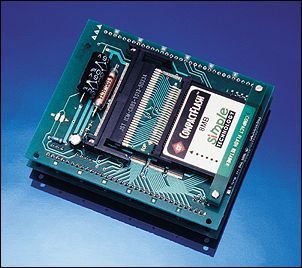
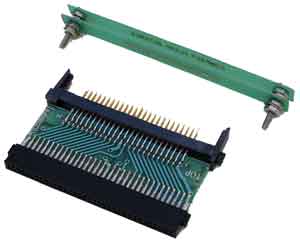
Compact Flash with converter and PCMCIA adapter |
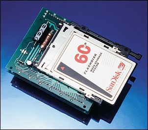
Flash-ATA card and PCMCIA adapter |
With this module you can quickly build tailor-made data collection systems with removable memory that can be read by a personal computer. It is an ideal way to save time and money designing custom loggers.
The TDS2020F computer card carries a TDS2020CM2 PCMCIA piggyback adapter. Add removable Flash-ATA, Compact Flash, RAM or hard disk memory cards as appropriate to the application. The amount of data you can collect is limited only by card capacity.
Data collected can be simply copied as a Windows file to your laptop or office hard disk (card drives for your personal computer are available, both internal and for connection to the parallel port). Alternatively recover data by connecting the module to a parallel printer, or send the information through a serial port, perhaps to a modem or over a telephone or radio link. See MODEMS, page 313.
Unlike PC solutions, the emphasis is on low power. The Flash or hard disk card is electrically disconnected most of the time. It is not even in standby: it consumes nothing. The software is written so that the storage card powers up as infrequently as possible. Between data readings the system itself may be put into standby so the Data Logger Module will consume less than 200�A most of the time.
A cache RAM on the TDS2020F ensures that the storage card does not have to power up very often. Eventually it will fill and in only 5 seconds a hard disk will spin-up, the computer will dump half a megabyte of data to disk, and the module will go back to standby. This short and infrequent operation takes a current of about 170mA at 12V for a hard disk but the long-term average remains in microamps. Solid-state Flash solutions are even faster, have lower operational current, and are as rugged as possible.
For data-logging applications you need to order these items:
q TDS2020F-SP Starter Pack, see SUGGESTED FIRST ORDER, page 36, for contents.
q
Select from
TDS2020CM2 PCMCIA adapter (standard
part-right-handed ejector)
TDS2020CM2LH PCMCIA adapter (left-handed
ejector)
TDS2020CM2NE PCMCIA adapter (no ejector
mechanism). This is the usual choice when using Compact Flash and the TDS2020CFA
converter.
q RAM512K or RAM128K to act as cache memory in the 32-pin socket. The larger RAM gives best performance because the time between disk use is greater.
q
An appropriate Flash or hard disk card. Order codes are as follows, the xxx
indicates the size:
-CMxxxMFLASHATA for PCMCIA-ATA Flash
cards
-CFxxxM for Compact Flash as used
in some digital cameras
-HDxxxM or HDxxxG for PCMCIA hard disks
q TDS2020CFA Compact Flash converter if using CF cards
q CF-PCA adapter to read Compact Flash cards in a notebook PC or PC attachment.
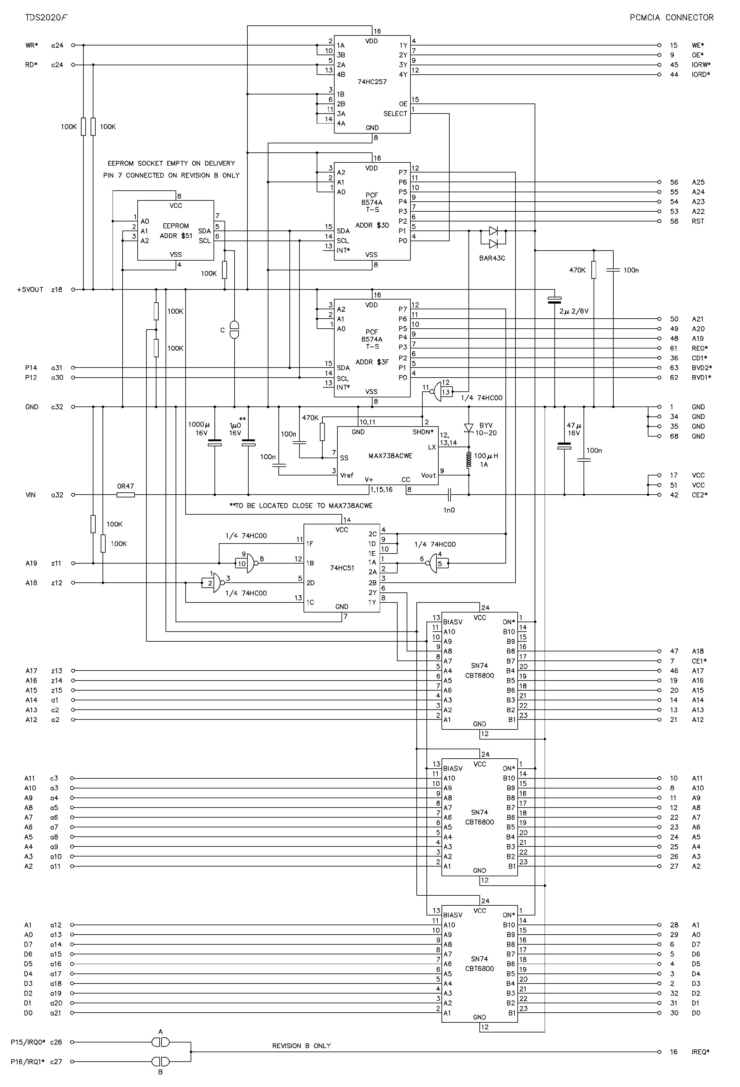 |
TDS2020CM2 PCMCIA adapter circuit diagram
Click the diagram for more detail, or to save a copy:
1. in Internet Explorer right click on the picture and select "Save Target as..."
2. in Netscape double-click the picture to open the file, then under "File"
select the "Save As" option.
Physically the double-board module has an overall size of 100 x 80mm. When mounted on a motherboard the bottom of the PCMCIA or Compact Flash card is 26mm above the base plane. The thick type III card (e.g. a hard disk) can take the overall height to 36.3mm.
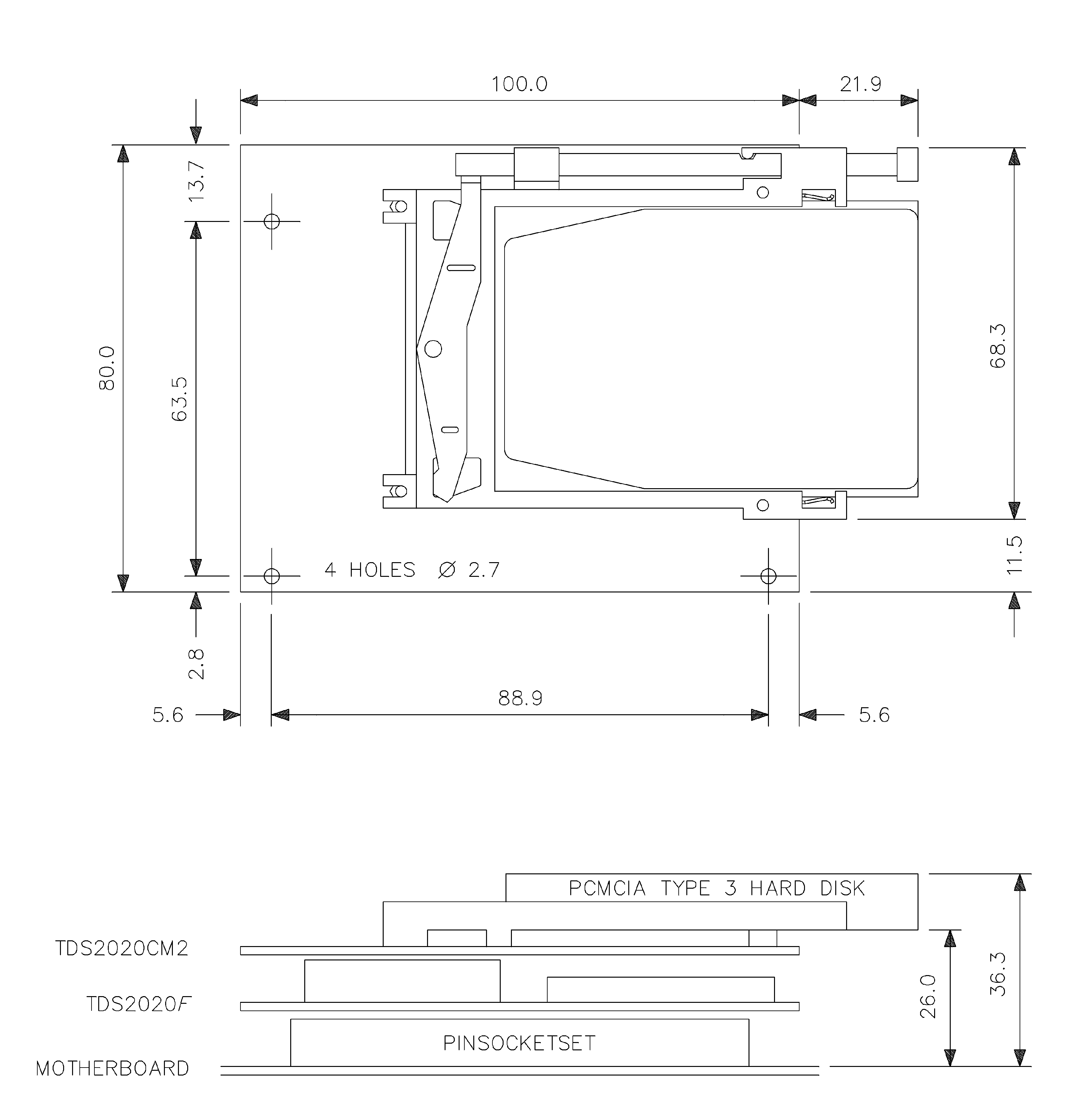 |
TDS2020CM2 physical dimensions
Click the diagram for more detail, or to save a copy:
1. in Internet Explorer right click on the picture and select "Save Target as..."
2. in Netscape double-click the picture to open the file, then under "File"
select the "Save As" option.
A single power supply of +6 to 16V is needed-there is an on-board switching converter to +5V. However because peak currents can be high the dynamic source impedance of the supply must be taken into account, the instantaneous voltage must not drop below 6V. It would be unwise to use a nominal voltage of below 9V when using a hard disk. A small rechargeable 12V battery will last for months in most circumstances.
The TDS2020CM2 needs less than 50�A power itself. The overall consumption of a module is typically the 32mA of the TDS2020F itself while collecting new data to the storage medium, but only 155�A in standby when not taking readings. The standby mode can be invoked 30 times second or more slowly, down to once per year.
Typical currents taken by a hard disk (not including the TDS2020F) are:
|
Power source |
9V |
12V |
15V |
|
Peak current |
350mA |
255mA |
213mA |
|
Idle (spinning) |
114mA |
85mA |
69mA |
|
Sleeping (after HD-OFF ) |
31mA |
25mA |
21mA |
|
Standby (after CM-OFF ) |
<50�A |
<50�A |
<50�A |
Flash-ATA and Compact Flash cards are the solid-state equivalents of hard disks. They present an identical electrical interface and work from a single +5V power supply. Flash-ATA cards have the 68 pins of the PCMCIA specification and Compact Flash 50 pins. Use a TDS2020CFA converter to mount Compact Flash cards on a TDS2020CM2 adapter and a CF-PCA adapter to read Compact Flash cards in a notebook PCMCIA slot.
 |
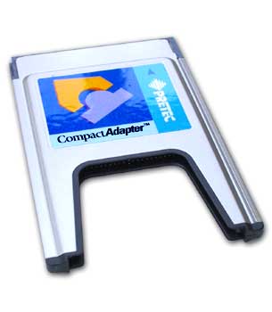 |
| TDS2020CFA for use with TDS2020F |
CF-PCA for use in a notebook PC |
Compact Flash to PCMCIA adapters |
|
Because these cards are electrically like hard disks (handling data in minimum chunks of 512-byte sectors), a cache RAM is needed in the 32-pin socket on the TDS2020F.
Flash-ATA and Compact Flash cards offer high capacity without the peak current and mechanical operation of a hard disk. They are more expensive per byte than rotating memory, but more rugged. They also nicely fill the gap in size between RAM and disk. Flash technology is known for the limited number of read/write cycles, but these cards claim to give 500,000 typical.
Miniature rotating memory is still important because it costs less. The Compact Flash format IBM Microdrive (1GB and 340MB) is approved for use with the TDS2020F+TDS2020CM2 Data Logger Module.
Apart from data collection, Flash cards are useful in read-only applications such as speech storage. For example a 4M byte Flash card can speak for over 10 minutes if the data is digitised every 150�s with 8-bit resolution. Alternatively use Flash cards for text or graphics messages as in a dynamic advertising display. You can then update the information presented by replacing the removable card or updating it over a communications link.
This software is not guaranteed to work with all PCMCIA and Compact Flash cards. The PCMCIA-ATA specification gives manufacturers various options. In particular the disk should support memory mode and byte mode access. Even then, a particular card may not be compatible with the low-level access methods used here. To be sure, we recommend use of memory cards that have been validated for use with TDS2020F. The preferred type is the industrial range from SanDisk, normally available from stock.
Before using the TDS2020CM2 PC card adapter first set up a TDS2020F computer, see FAST START GUIDE, page 12, and ensure it is working correctly.
The TDS2020CM2 plugs into the top of the TDS2020F computer (but there isn't a version for the TDS2020F-PLUG). Be careful when putting the two together, checking the following points:
q Place a 128k byte or 512k byte RAM in the 32-pin socket. This acts as a disk cache to avoid unnecessary accesses, saving time and reducing power consumption. Data is put in these buffers and the disk is only powered up for the write operation when they are full.
q Ensure all pins on the TDS2020CM2 are straight. If not, touch a ground point (anti-static protection) and align them with fine pliers.
q Make sure the boards are the same way round. The double row on the TDS2020CM2 matches the double row on the TDS2020F.
q Put pin 1 to pin 1, it is easy to misalign the two cards and get pin 1 into pin 2 by mistake.
q Make no changes to the original link settings on either card. In particular, leave link P connected and link Q open.
Before reconnecting power examine the sandwich to make sure the two cards are the same way round and exactly over each other, not staggered. Reattach power and ensure that the computer is still operating correctly.
Put a Flash-ATA or hard disk PC card in the slot, or use a Compact Flash card with the TDS2020CFA converter. Be sure each component is the right way up-the TDS2020CFA has the word TOP on one side. Now compile the file #DOSHD.TDS provided and test by typing LAYOUT . You should see a map of the card looking something like this (the example is a 4MB Flash-ATA card).
Partition table: sector 0
Boot sector: sector 16
File allocation table (FAT): sector 17
Dictionary: sector 23
Data in file DATA.FIL starts: sector 37
Max size of file DATA.FIL: bytes 3978752
Last physical sector: sector 7999
Unformatted disk size: bytes 4096000
You can use SEE to look at any sector as follows to gain confidence that the module is operational. Use a double (32-bit) for the sector number, for example:
0. SEE to view partition
table (both Flash and Hard Disks have one)
16. SEE to view the DOS boot
sector
On the TDS2020CM2 adapter two PCF8574A parallel I/O chips are used on the I2C bus to receive page data and return status information. They have I2C chip addresses $3D and $3F. There can be only up to eight PCF8574A chips and eight PCF8574 chips on the I2C bus. In adding more externally you are limited to only 14 instead of 16 of these chips. Note that no ports or address decodes on the computer are needed, all are still available for your own use.
An empty socket on the TDS2020CM2 adapter can hold an 8-pin Flash or EEPROM chip. Many data loggers need semi-permanent configuration information and this is the place to put it. Some possibilities are:
q 24WC256, a 32k byte chip from Catalyst
q 24C65, an 8k byte chip from Microchip
q PCF8582, a 256 byte chip from Philips
Driver files for these are in the software library. The chip is on the I2C bus of the TDS2020F; use chip address $51 with the words provided in the appropriate file.
There is now a variety of EEPROMs and Flash chips suitable for insertion in this socket. Most pin connections are identical, but for some you need to make link C to ground pin 7 to give particular functions. The table below shows some pin 7 connections, but please check the individual data sheet.
|
Manufacturer |
Function |
Device |
Pin 7 |
|
Microchip |
256 byte EEPROM |
24C02A |
0V |
|
|
8k byte EEPROM |
24C65 |
+5V 0V or NC |
|
|
256 byte EEPROM |
85C82 |
+5V 0V or NC |
|
Philips |
256 byte EEPROM |
PCF8582C-2 |
+5V or NC |
|
SGS-Thomson |
16k byte EEPROM |
M24128 |
0V or NC |
|
|
32k byte EEPROM |
M24256 |
0V or NC |
|
|
256 byte EEPROM |
ST24C02A |
+5V or NC |
|
|
8k byte EEPROM |
M24C64 |
+5V or 0V |
|
|
4k byte EEPROM |
M24C32 |
+5V or 0V |
|
Xicor |
2k byte EEPROM |
X24C16 |
0V |
|
|
16k byte Flash |
X24F128 |
+5V 0V or NC |
|
Catalyst |
32k byte EEPROM |
24WC256 |
0V |
Identical support files are used for all of the following. RAM cards are different, see DATA LOGGING TO RAM PCMCIA CARDS, page 274.
q Flash-ATA cards
q Compact Flash cards
q Hard disk cards
The library files in question are:
|
#CARDHD.TDS |
Low-level disk access-transfer data between absolute sector numbers and memory |
|
#DOSHD.TDS |
Provides Windows and DOS emulation so that the card can be formatted and read in a PC with Explorer or Windows applications like Excel. |
Files #DOS.TDS, #FDISK.TDS and #TIMED.TDS may also be called during compilation.
The disk can be Windows formatted either on a PC or in the module. Then an empty file DATA.FIL is put onto the disk. These are the main strategies for data collection:
q Extend DATA.FIL during data collection.
q Extend DATA.FIL to a fixed size, perhaps the whole card, after formatting. Logging will be faster because the Windows File Allocation Table (FAT) does not have to be updated while data logging.
q Use a lower-level routine that transfers data between 32-bit addresses in the computer and specified sectors storage card. One command transfers from 1 to 255 sectors of 512 bytes each at about 230,000 bytes per second.
Only one file is provided for the first two methods. This avoids the execution time and memory space burden of full Windows file emulation. You can mark the end of each 'run' in the file and after recovery into a PC use a simple program to identify the markers and split the original single file into many, each being a single 'run'.
This list summarises the key operations:
q To Windows format a card in a TDS2020F use HARD-FORMAT . This also partitions the disk and writes an empty file DATA.FIL. Do not use a card memory formatted on TDS2020F (or on which you have logged data) for any normal PC purpose without reformatting on a PC.
q
To Windows format a card in PC:
1. Partition the card with FDISK, ATAINIT,
PCMFDISK or equivalent. Even Compact Flash cards are equivalent to hard disks
and have a partition table.
2. Use the command FORMAT x: where x is the drive letter of the
PCMCIA slot. When asked for a volume name do not give one, just press return.
Some PCMCIA drivers have their own specific format methods, see your PC documentation.
3. Use the PC routine DATAFILH.EXE to write an empty single file DATA.FIL to
the disk.
q To pre-allocate a data collection file to make logging faster use xxx MB . It extends the hard disk file DATA.FIL by xxx megabytes. No data is written into the file, it takes up the data previously on the disk in the space which it occupies.
q To initialise the module use HARD in the power-up word. Also type it interactively after compiling #CARDHD.TDS or #DOSHD.TDS. It sets up hardware and software and also identifies the start of the file DATA.FIL.
q
To log data the alternatives are
as follows:
1. Use HARDEMIT
to store the next character
2. Redirect serial output to the hard disk with the word <HARD and end redirection
with HARD>
.
3. Use TRANSFER
to write data from anywhere in memory to specific sectors on the storage
card.
q To update the date and time of DATA.FIL use the word STAMP .
q To read collected data into a PC use any Windows copy facility. For example use Explorer to transfer the file DATA.FIL from the storage card to the PC.
q To serially output collected data use SQUIRT , which outputs the whole of file DATA.FIL to the TDS2020F's serial port 1.
q To view Attribute memory space issue ATTRIBUTE and use HARD to revert to regular memory space.
q To view I/O space issue IO and use HARD to revert to regular memory space.
Solid state Flash-ATA and Compact Flash do not have the spin-up and spin-down times of hard disks. Furthermore, eliminating the retries built into the word TRANSFER (and similar shortcuts) can shorten access times, but that is not reflected below. Also see further timings in the file #CARDHD.TDS.
q Awake from standby and read a sector typically 3.24s (hard disk) and 0.19s (Flash-ATA or Compact Flash).
q Write per 512 byte sector typically 2.09 ms (hard disk, Flash-ATA or Compact Flash).
q Awake disk, dump 496k bytes of data to DOS formatted disk and go back to standby typically 5.7s (hard disk) and 2.6s (Flash-ATA or Compact Flash) plus 75ms for every megabyte already written on the card (FAT extension time).
q Using TRANSFER to record sectors without DOS: Throughput with standby between dumps typically 95,000 bytes/sec (hard disk) and 207,000 bytes/s (Flash-ATA or Compact Flash). Maximum sustainable throughput typically 230,000 bytes/s (disk, Flash-ATA or Compact Flash)
q Time for EMIT when redirected by <HARD typically 56�s.
q Worst case maximum throughput using <HARD . HARD> redirection typically 11,500 bytes/s on a 130Mb hard disk (without the time for data input), 7,000 bytes/s on a 512Mb hard disk and 15,600 bytes/s on a 20Mb Flash-ATA or Compact Flash card.
The 32-bit constants CACHE and CACHE-SIZE determine where disk buffers will be located in the 32-pin RAM and can be changed by the user before compilation, depending on the size of RAM fitted in the 32-pin socket. By default, the software is set for a 512k byte RAM. If you use a 128k byte device for the cache edit the defining addresses in file #CARDHD.TDS.
Take note if you use #EXTVAR.TDS or #EXTVALU.TDS to get extra variables in extended memory. The default constants in the included file #CARDHD.TDS are set to use most of the RAM in the 32-pin socket for disk buffers and scratch memory. The RAM from hex FC200 to FFFFF is still free and you can use it by changing the line at the start of these files from 0 VDP ! to $C200 VDP ! .
Words to partition and format Flash-ATA, Compact Flash and hard disks are in a separate file #FDISK.TDS automatically compiled near the end of file #DOSHD.TDS. You can save code space by commenting out the INCLUDE statement if formatting will only be done on a PC. On the TDS2020F you can use HARD-FORMAT to format the disk but a few PC drives will not read this formatting correctly, so if you format on the TDS2020F be sure that your PC will read the resulting data files before using the system in the field.
Any Flash-ATA or Compact Flash card can be written with either 12-bit or 16-bit File Allocation Tables (FATs). 12-bit was the only option many years ago when all disks were below 32 megabytes. The decision on FAT structure is made when the unit is partitioned and formatted. The software #DOSHD.TDS determines the type from the card and logs data with 12-bit or 16-bit FATs as appropriate to its formatting. PC readers should be able to read both but some will not. It seems most modern PCs will read either 12-bit or 16-bit formatted PCMCIA cards, but some older designs will not read 16-bit FATs from a PCMCIA card that is under 32 megabytes.
HARD-FORMAT lays down a 12-bit FAT for cards under 32 megabytes and a 16-bit FAT for larger ones. If you have difficulty in reading the card, format it on the PC you intend to use for data recovery.
Use the words <HARD and HARD> in pairs within one Forth word. Any output made by words such as EMIT . .R D.R ." etc. will be sent to the disk. For an example, see MODEL PROGRAM-LOW POWER DATA LOGGING, page 267. If you need to temporarily switch output back to serial Port 1 within a <HARD . HARD> structure, use the words <1 and 1> like this:
<HARD . <1 . 1> . <1 . 1> . HARD>
Successive data logging runs will be in a single file DATA.FIL on the disk and occupy an integral number of clusters. The actual termination of each data run can be seen from the message written by HARD> after each cycle and there may be some junk data after it up to the end of the current cluster. You can edit the text of the record marker in the definition of HARD> . Once in the PC, the copy of DATA.FIL can be readily split into several files if required by a text editor (in the case of CSV logging) or a simple BASIC program. The marker from HARD> becomes the end of each file.
An alternative way is to use MB to extend the empty file DATA.FIL after formatting (see PRINCIPAL OPERATIONS, page 259). E.g. 10 MB to get a 10-megabyte file. Now use the hard disk primitive TRANSFER (in file #CARDHD.TDS) to directly write to sectors within the file DATA.FIL. This is a much faster way because the disk does not have to update the File Allocation Table (FAT) at run-time.
Another use for MB is in recovery of data from a disk where there is corruption of the partition sector, boot sector, File Allocation Table or dictionary. Formatting on TDS2020F does not alter the logged data on the disk so you may be able to recover it from an apparently corrupt disk like this:
HARD-FORMAT 100 MB
This example will rewrite the DOS information and recover the first 100 megabytes of data into the file DATA.FIL. Alternatively, you could format on the PC, then use 100 MB to extend the default file.
The size of the logging file DATA.FIL can be set to zero bytes with DELETE , even if the partitioning and formatting software in #FDISK.TDS has not been compiled to save dictionary space. Note that the actual data is not removed, the file may be recovered using xxx MB if accidentally deleted. For example use 100 MB to remake DATA.FIL containing the first 100 megabytes of data.
If you are logging serial input data (with any method of data logging) use the file #SHELTER.TDS or #EXTSHEL.TDS to get an interrupt-driven serial buffer. That way you do not lose input while data is being written to disk. The only change you need make to your own software is to put the initialisation word SHELTER into the word executed at power-up. However, you may have to edit the position and size of the circular buffer set up inside whichever of the two library files you are using. The interrupt-driven serial support files come with the Update Service. See file #232LOG.TDS for an example.
To read the Flash-ATA, Compact Flash or hard disk in a PC or portable use the DOS command COPY or Windows Explorer to copy the file DATA.FIL to the PC's hard disk. For example:
COPY D:DATA.FIL C:
Do not examine the data directly on the card with any other program, or write any other files to the PCMCIA card. The format of the file there uses only a subset of the Windows file structure and direct access may corrupt it. Copy the file, then look at the copy.
Data on Flash-ATA, Compact Flash or hard disks can be read and output from serial Port 1 on a TDS2020F computer. The word SQUIRT will examine the size of the file DATA.FIL and output each printable byte. If the data is binary and may contain non-printable characters, modify SQUIRT as appropriate.
Data collection usually must be done at regular intervals. Here we review the options available to help choose the best scheme for the application. They fall into five broad categories that will be discussed in turn, followed by details of how to synchronise with the hour or minute.
q Slowest, least power. Low power software standby that is periodically awakened by non-masked interrupts (NMI) from the clock chip.
q Intermediate. Regular interrupt that stacks the current Forth system and creates a new one for the duration of the interrupt.
q Intermediate. Regular interrupt that does very little except set a flag that it has happened, ready for a foreground program to do the actual work.
q Faster, more power. Do the data collection inside the interrupt.
q Fastest, no interrupts. Abandon everything else for sheer speed.
In the following table, focus on the type that is closest to your required speed of data collection. You can see which library files are near to your needs and tell if a foreground program will be possible in addition to the data collection operation.
|
Type |
Library files |
Samples/sec |
Foreground? |
|
Least power (standby) |
#TIMED.TDS |
0-30 |
No |
|
|
#DOSHD.TDS |
|
|
|
|
#DATALOG.TDS |
|
|
|
|
|
|
|
|
Forth interrupts, |
#EVERY.TDS |
0-10 |
Yes |
|
multiple events |
#MT.TDS |
10-2,000 |
|
|
|
|
|
|
|
Assembler signalling |
#REGULAR.TDS |
20-10,000 |
No |
|
|
|
|
|
|
Assembler interrupts |
#DOSDUAL.TDS |
1,000-100,000 |
Yes |
|
|
#FASTLOG.TDS |
|
|
|
|
#REGULAR.TDS |
|
|
|
|
#FASTAD.TDS |
|
|
|
|
|
|
|
|
Fastest, no interrupts |
#FASTEST.TDS |
10,000-364,342 |
No |
The advantage is that the TDS2020F/TDS2020CM2 module in standby mode takes only about 200�A current. If we leave the data logger in standby most of the time the overall power consumption will be very low.
The disadvantage is that nothing except the board clock is working while the device is in standby. The microprocessor and all its on-board peripherals are inactive.
The words in file #TIMED.TDS allow a loop to be executed with any period from 30ms to 99 days-sampling slower than 30 times per second. After one set of data is collected, use the Forth words provided to put the processor into standby and to repeat the loop after an exact interval.
If using Compact Flash or Flash-ATA cards go for #DOSHD.TDS that has a demonstration program using this technique, see MODEL PROGRAM-LOW POWER DATA LOGGING, page 267. See also file #DATALOG.TDS.
The advantage is that the foreground is left free, for example for interactive Forth that can be used to extract data from the data logger without stopping the data collection process.
The disadvantage is that time is taken on each interrupt to swap the Forth system for a new one. This gives an entry and exit overhead at each interrupt of about 73�s (81�s using TDS2020DV). In addition, the data logging itself is in Forth (unless you package it in an assembler word). For these reasons, the technique is not suitable for fast work.
q For data collection rates of about 10 to 2000 samples per second, use the LATER mechanism seen in file #MT.TDS.
q For 10 samples per second down to one per 54 minutes, possibly with multiple events such as one on the quarter hour and another every half-hour, use file #EVERY.TDS.
In either case power can be saved if a foreground program is not required. The standby mode cannot be used because only NMI or reset can awaken it. However, the sleep mode can be awakened by the output compare interrupts used in the files shown above. It saves about half the power, a TDS2020F can run at currents down to about 16mA. File #EVERY.TDS has an example of its use. See INTERRUPT MULTITASKING EXPLAINED, page 182.
The advantage is that the time overhead for each assembler interrupt is low. It only allows the foreground to progress round its loop, the interrupt does nothing inside itself. Since the data collection itself is written in Forth, no assembler knowledge is necessary.
The disadvantage is you cannot have a separate foreground program. The system will be dedicated to data collection.
Base your code on file #REGULAR.TDS. It can be used from about 20 to 10,000 samples per second and is often the best choice for data collection at the top end of this range. The overhead of each interrupt is only 18�s. The sleep mode is part of this technique-the TDS2020F runs at currents down to about 16mA.
The advantage is that there is no overhead apart from the setting up of the regular interrupt. The customised data collection code can be put right after the housekeeping of the interrupt. Another advantage is that you can have a foreground program, for instance interactive Forth.
The disadvantage is you have to code the data collection part in assembler. It is not difficult and advice and assistance are available.
You can base the fast data collection on #DOSDUAL.TDS if using Compact Flash or Flash-ATA cards. Otherwise, use #FASTLOG.TDS or #REGULAR.TDS, adding custom collection code inside the interrupt. Alternatively, look at #FASTAD.TDS. Collection rates up to about 100,000 bytes per second are possible. However, because of the possibility of a simultaneous foreground program, the technique is useful down to 1,000 samples per second.
The file #FASTEST.TDS gives data collection speeds possible only into RAM chips. See USING RAM CHIPS, page 281.
Some of the techniques above will log data every quarter of an hour, but you are unlikely to want records at 10.07, 10.22, 10.37 etc. It would be better if they were at 10.15, 10.30, 10.45 etc. Whatever the method used for data collection, there is code in file #TIMED.TDS for achieving this. To wait so that the first record will be at a rounded time, include file #TIMED.TDS and use O'CLOCK . For example, before the start of the logging loop put 20 SECOND O'CLOCK . If the program is started at 10.30.07 the first record will be logged at 10.30.20, the next at 10.30.40 and so on. Another example: to log on the hour, use 1 HOUR O'CLOCK . While waiting, the TDS2020F will be in standby most of the time.
This demonstration from #DOSHD.TDS is applicable when low power is needed and records are taken between 30 times second and once per year. It illustrates the principles behind many data logging programs and also acts as a system test routine. It records the numbers 0 upwards every 5 seconds in ASCII format. In a real application the numbers generated in the loop would come from input transducers etc.
: DATALOG ( - )
5 SECOND O'CLOCK \ set, and wait for, rounded
\ loop time;
<HARD \ redirect output to PC card
0 \ primer for output numbers
BEGIN \ start of loop
<1 \ redirect back to serial
CR W@ .TIME \ send time to serial port
2 SPACES 10 MS \ and wait for text to go
1> \ back to PC card again
SUSPEND \ go to low power mode
1+ DUP 8 U.R \ output numbers in
\ sequence to PCMCIA
200 MS KEY? \ to exit on any key
UNTIL KEY \ discard keystroke and
2DROP \ incrementing number
HARD> ; \ cancel redirection
5 SECOND O'CLOCK will wait until the next 'round' time. A loop delay for SUSPEND of 5 seconds will be set.
Inside the <HARD . HARD> structure all output is redirected to the card memory, except if it is temporarily redirected elsewhere, as in the <1 . 1> structure in this example, put here just to view the logging progress on serial Port 1. It would be erased in the final application. Note the 10 MS needed before terminating output to the serial port-time must be allowed for the last character to be transmitted.
The program rests in SUSPEND for most of the time and the module is in standby consuming little power. In fast applications it must be omitted and the loop time determined by software execution time. An alternative is to use the sleep mode, see file #REGULAR.TDS.
No useful data collection is done in this demonstration by 1+ DUP 8 U.R , the numbers 0, 1, 2, 3 etc. are output to the card memory as simulated data, each in a field 8 wide and right justified. You can substitute your own data gathering code here. Use any words that you normally employ to display to the PC, they will all be redirected to the card memory. Examples are:
." end of log" .TIME . 10 D.R ", EMIT
The last example above shows how a comma can be added after a number to make DATA.FIL into a comma-separated-variable (CSV) file. The ASCII value of comma is sent to the card memory. CSV files can be directly opened in Excel, see EXAMPLE DATA LOGGING PROGRAM, page 269, GLOBAL POSITIONING SYSTEM, page 319 and files #DATALOG.TDS & #GPSLOG.TDS. To log binary (as opposed to ASCII) data use an EMIT for each byte collected.
On exit the final HARD> not only terminates redirection to the PC card, it flushes any remaining data in the RAM cache and adds a marker to the end of this 'run' so that DATA.FIL can be split later in the PC.
After running DATALOG you can put the memory card in a PC and copy DATA.FIL. Open it in a text editor to see the pseudo-logged data.
The above method has the disadvantage that every so often sending just one byte will overflow the RAM cache, causing up to 512k bytes of data to be flushed to the card memory, potentially a delay of a few seconds. File #DOSDUAL.TDS provides continuous fast data collection, without this hiccup. This is achieved by splitting the cache into two. One is used for data collection under interrupt, while data in the other buffer is being transferred to the PCMCIA card by the foreground routine (or another task if the multitasker is installed). Data collection speeds of over 100,000 bytes per second can be achieved. If you want to use this mode of operation, first compile #DOSHD.TDS and then #DOSDUAL.TDS.
Click here for the complete program #DATALOG.TDS in the software library.
 |
|